Arduino I2C Scanner and LCD Project
Level 60 · Who's on the Bus · 30 minutes
Discover an LCD and a clock on the same two signal wires. Scan their addresses, then show what you found.
Preview the project free; a course seat is required to run and submit. No hardware kit needed.
Your project challenge
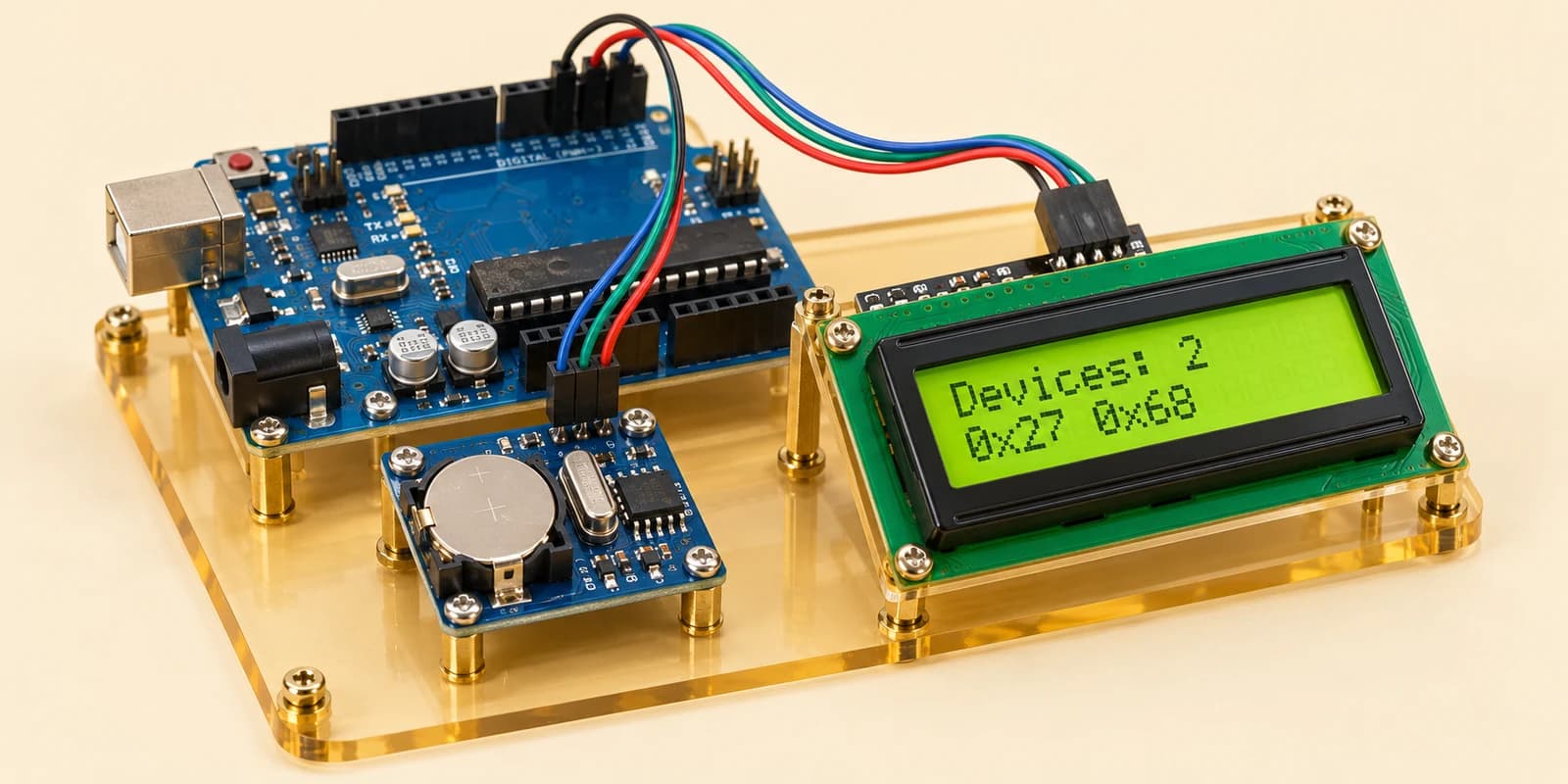
Connect both modules to the same SDA (A4) and SCL (A5) wires. Scan addresses 1–126. Print each responding address to Serial. Show Devices: 2 on the LCD’s first row and 0x27 0x68 on its second row. Use the scan results, not a fixed list.
Components you’ll use
- Arduino Uno
- I²C LCD (16×2)
- DS1307 I²C Clock
What you’ll build
A device finder: one Arduino talks to an LCD and a clock over two shared signal wires. Follow all eight wiring steps, then start the simulation. The screen shows the devices it finds; open Serial to see their addresses.
How it works
I²C uses SDA for data and SCL for timing. Each device listens for its own address. The LCD here answers at 0x27; the clock answers at 0x68. These are hexadecimal numbers, not pin numbers.
The key idea
Try each address with Wire.beginTransmission(address). A zero from Wire.endTransmission() means a device acknowledged. Count those replies and save their addresses for the screen.
⚠ Watch out
Both modules need 5V and GND as well as SDA and SCL. Two devices cannot share the same address. This lesson discovers the clock; setting its time comes later.
Try it: stop, disconnect the clock’s SDA wire and run again. The count should become one. Reconnect it before submitting.
The interactive editor includes the wiring guide, code editor and simulation controls.