Arduino 4x4 Keypad
Level 20 · Level 20 — Type It · 25 minutes
Eight pins read sixteen keys, by driving one row at a time and watching which column answers.
Preview the project free; a course seat is required to run and submit. No hardware kit needed.
Your project challenge
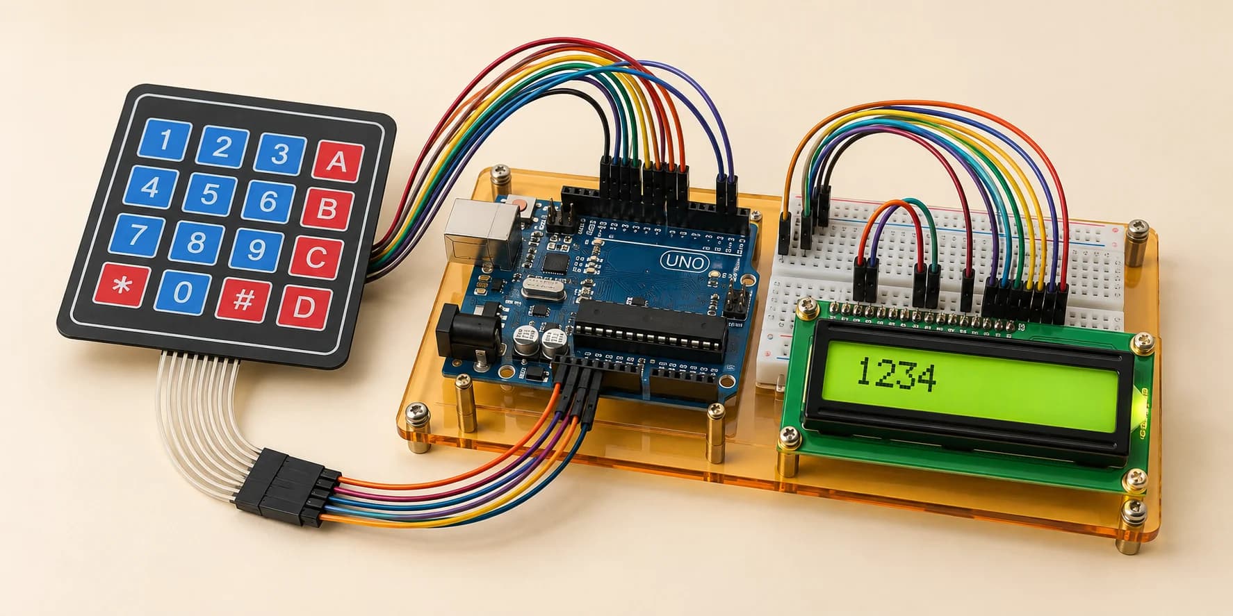
Type four keys onto the screen. Wire it up: - LCD as in Level 17: RS to D12, E to D11, D4-D7 to D5/D4/D3/D2 - RW to GND, or the screen stays blank. V0 to GND too, for contrast - Keypad: rows 1-4 to D6-D9, columns 1-4 to A0-A3 Put "Code" on top. Echo each key onto the bottom line, in order.
Components you’ll use
- Arduino Uno
- LCD 16x2 Display
- 4x4 Membrane Keypad
What you'll build
A keypad you type on. An LCD that shows it.
How it works
- Four rows cross four columns: sixteen crossings.
- Pressing a key joins its row wire to its column wire. Nothing else.
- So you cannot ask the pad which key is down. You scan it.
- Rows idle high on INPUT_PULLUP, a resistor inside the chip.
- Drive one column low: a row reading low is a pressed key.
That is matrix scanning. Your keyboard reads a hundred keys through about twenty wires.
The key idea
The matrix is not a saving. It is the only way this fits:
18 usable pins - 6 for the LCD = 12 free
16 keys need 16 pins. A matrix needs 8.
Only six are D pins, so columns go on A0-A3.
⚠ Watch out
A held key is down on every later scan. Echo the raw scan and one 120ms press fills the line: 2222222222222222, not 24C#. getKey() answers only when a key changes to pressed.
Swap two row wires and all four keys still type, two as the wrong letter. Put a row wire on a column pin and those two keys go silent: the line comes back short.
The interactive editor includes the wiring guide, code editor and simulation controls.