Arduino Alarm Clock with DS1302 RTC, Keypad and Buzzer
Level 51 · Wake Me · 30 minutes
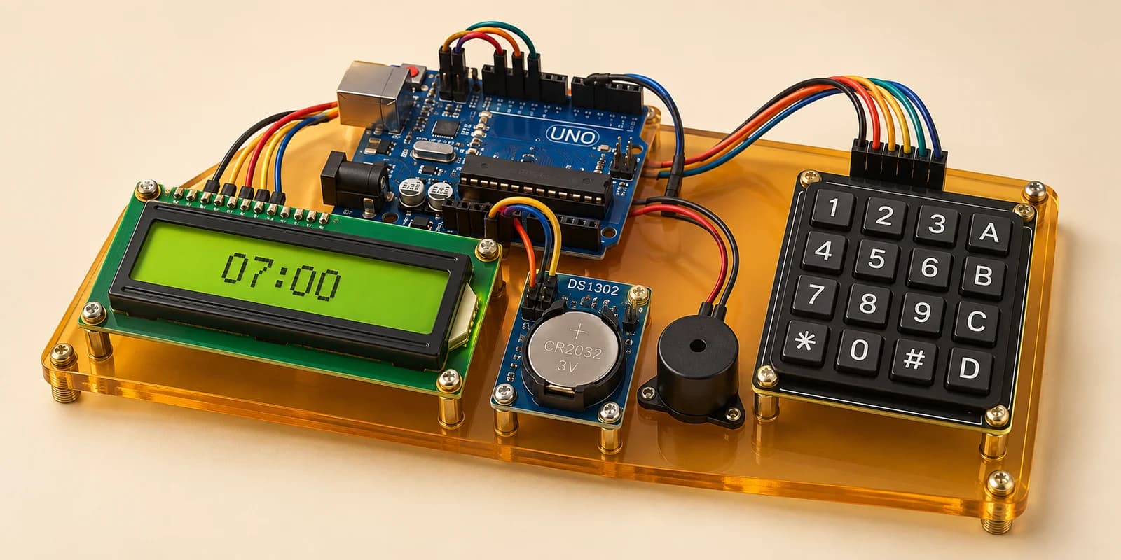
An alarm clock: the screen shows the clock chip’s time, the keypad sets the alarm, and the buzzer beeps until you press *.
Preview the project free; a course seat is required to run and submit. No hardware kit needed.
Your project challenge
Make an alarm clock. Wire it up: - LCD and keypad on the same pins as before - Clock module: VCC 5V, GND, CLK A5, DAT A4, RST D10 - Buzzer: pin1 to D13, pin2 to GND Show the clock time as HH:MM:SS on the top line. Type HHMM and # to set the alarm. Beep until * is pressed.
Components you’ll use
- Arduino Uno
- LCD 16x2 Display
- 4x4 Membrane Keypad
- DS1302 Real-Time Clock
- Piezo Buzzer
What you’ll build
An alarm clock. The screen shows the time. You type the alarm on the keypad, and the buzzer wakes you.
How it works
- The DS1302 clock chip counts seconds on its own crystal. A coin cell keeps it counting when the power is off.
- The sketch never sets the time. It only reads it with
rtc.GetDateTime(). - Type four digits, HHMM, in 24-hour time.
0630is half past six in the morning. Then press # to set it. - When the alarm goes off, the buzzer beeps until you press *.
The key idea
Check the alarm only at the moment the minute changes:
if (now.Minute() != lastMinute)
Then compare the new hour and minute with the alarm.
⚠ Watch out
If you ring “while the minute matches”, * stops the buzzer and it starts again at once. It keeps going for the whole minute. Do not use millis() to count the time either. Only the chip knows what time it really is.
The interactive editor includes the wiring guide, code editor and simulation controls.