Arduino RFID Door Lock with RC522 Card Reader
Level 69 · Tap to Enter · 40 minutes
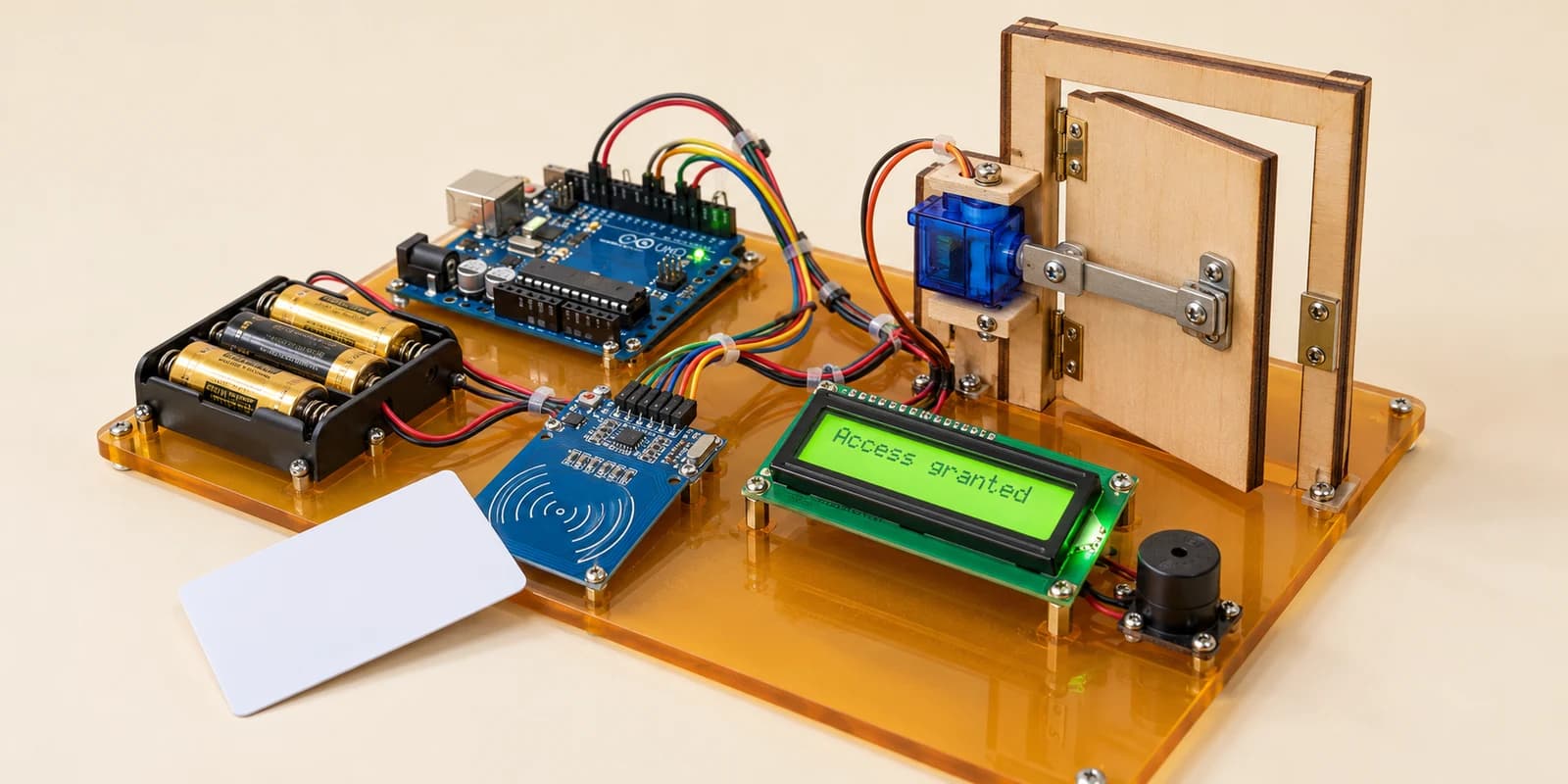
Build an RFID door lock. Recognise a member card, reject visitors, unlock for two seconds and relock even if the card stays on the reader.
Preview the project free; a course seat is required to run and submit. No hardware kit needed.
Your project challenge
Present cards using the reader controls. Only UID DE AD BE EF unlocks the servo to 90° for two seconds. Relock to 0° even if the card stays present. Show Access granted or Access denied on the LCD and beep once. Remove a card before tapping again. Compare all four UID bytes.
Components you’ll use
- Arduino Uno
- RC522 RFID Reader
- SG90 Micro Servo
- Battery
- I²C LCD (16×2)
- Piezo Buzzer
What you’ll build
An RFID access-control model with a moving latch. Start the simulation, then use the reader’s Member card or Visitor card button. Watch the LCD and the door panel. Press Remove card before presenting another.
How it works
The RC522 uses SPI: D11 sends data, D12 receives it, D13 clocks it and D10 selects it. Its SDA pin is labelled for another interface; in this lesson it is SS, not A4. RST goes to D8 and power to 3V3. IRQ stays unused.
Your code
MFRC522 reads the card UID. Compare its length and all four bytes with DE AD BE EF. An accepted card turns the servo to 90° and shows Access granted. After two seconds, return to 0° and Tap your card. A rejected card shows Access denied. Halt the card after handling it so holding it still is not another tap.
Try it
Leave the member card present and wait: the latch must still lock. Remove it and tap again. Try the visitor card; the latch must stay locked.
Real hardware
This is a learning model, not a secure door system: UIDs can be copied. Physical RC522 boards need 3.3V-compatible signal levels; use level shifting with a 5V Uno. The simulator checks wiring and supply rails but does not model voltage damage.
The interactive editor includes the wiring guide, code editor and simulation controls.